Remote trigger module
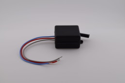
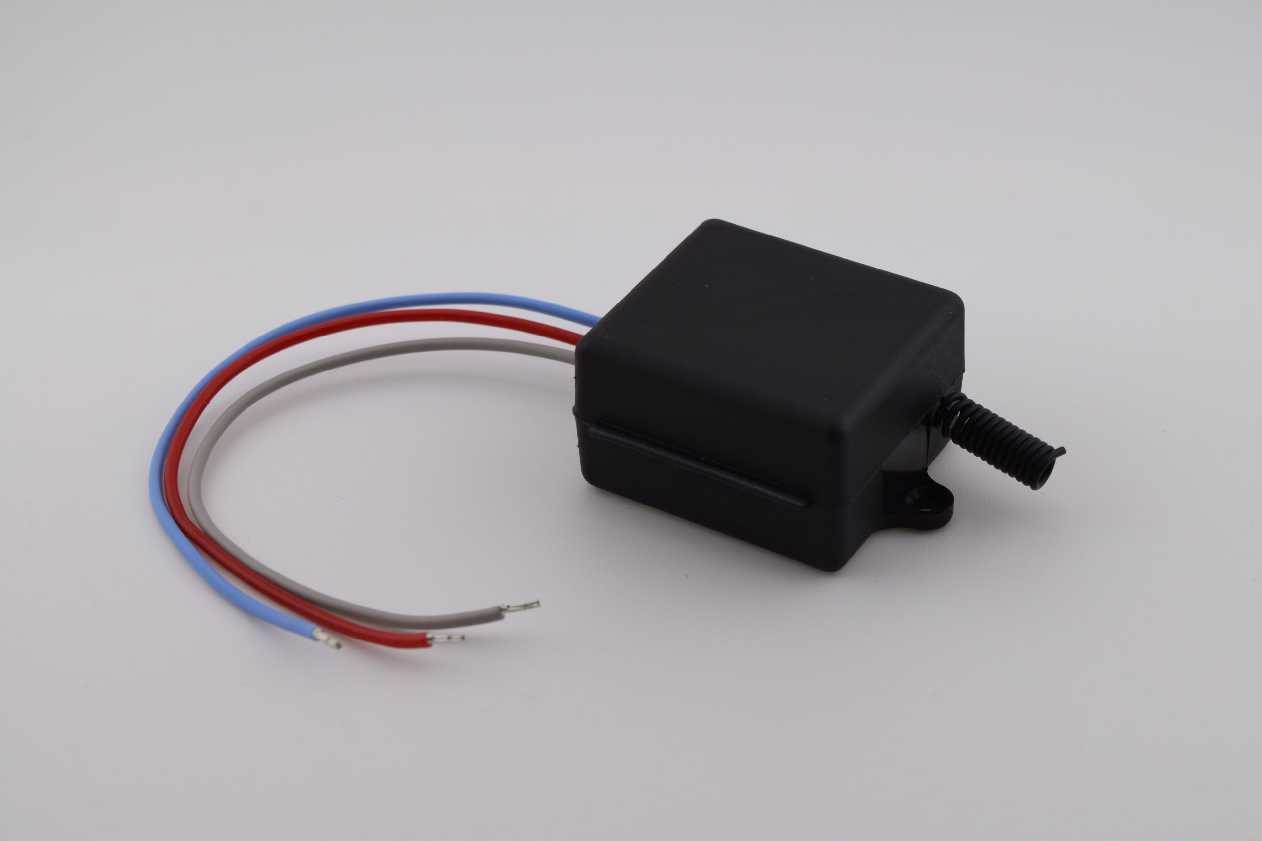

RF 433 MHz Module – KR3001A
Technical data
| Power supply: | 5 – 60 V DC |
| Housing: | Compact module |
| Dimensions: | 35 x 30 x 18 mm (L x W x H) |
| Weight: | – |
| Operating temperature: | -10 °C to +80 °C |
| Interfaces: | RF 433.92 MHz |
Description:
Radio option – Wireless traffic light control
This module is available as an option on the V60 and V100 displays. It enables wireless control of the red and green lights integrated into the display, with no cabling required between the control station and the remote display.
Accessories:
-
RF 433 MHz remote controls
Several models available depending on design and range. Range is significantly improved when the antenna is placed outside the remote control. - External power supply DC 5 – 60 V
Documentation – KR3001A Module
Table of contents
- 1. Product description
- 2. Electrical characteristics
- 3. Wiring
- 4. Operating mode configuration
- 5. Reset function
1. Product description
This module is available as an option on the V60 and V100 displays. It enables wireless control of the red and green lights integrated into the display, with no cabling required between the control station and the remote display. It supports four operating modes selectable by the user.
2. Electrical characteristics
| Parameter | Value |
|---|---|
| Supply voltage | DC 5 – 60 V |
| RF frequency | 433.92 MHz ASK |
| Standby current | ~5 mA |
| Rated load | Max 600 W |
| Relay current | Up to 10 A |
| Receiver sensitivity | -97 dBm |
| Range (theoretical) | 80 – 100 m |
| Operating modes | Momentary / Toggle / Latching / Delay |
| Operating temperature | -10 °C to +80 °C |
| Dimensions (L x W x H) | 35 x 30 x 18 mm |
3. Wiring
⚠ Switch off power before any wiring.
⚠ Never reverse the +V and -V terminals.
The module connects directly to the display connector as follows:
| Display – Terminal | Signal | RF Module – Terminal | Colour |
|---|---|---|---|
| 3 | GND | V− | Black |
| 8 | +5V | V+ | Red |
| 7 | Green | NO | Green |
| 6 | Red | NC | Red |
The module relay switches the GPIO signal of the display. When the relay is activated via the remote control, it connects COM to NO, linking the Red or Green terminal of the display and turning on the corresponding light.
4. Operating mode configuration
The mode is selected via the LEARN button on the module. The number of successive presses determines the activated mode, confirmed by the blinking of the status LED. Once configured, the mode is retained even after a power cut.
Note: pairing a second remote control does not require resetting the mode. Compatibility is guaranteed only with QIACHIP brand remote controls.
4.1 Mode summary
| No. of LEARN presses | Mode | Relay behaviour |
|---|---|---|
| 1 press | Momentary | Active while the remote control button is held down |
| 2 presses | Toggle | One press activates, a second press deactivates |
| 3 presses | Latching | Button A = activate, button B = deactivate (2 buttons required) |
| 4 presses | Delay 5 s | Relay closed for 5 seconds after command |
| 5 presses | Delay 10 s | Relay closed for 10 seconds after command |
| 6 presses | Delay 15 s | Relay closed for 15 seconds after command |
| 7 presses | Delay 20 s | Relay closed for 20 seconds after command |
| 8 presses | Reset | Clears all paired remote controls and resets the mode |
4.2 Momentary mode
In this mode, the relay is activated only while the remote control button is held down. It deactivates as soon as the button is released.
4.2.1 Configuration procedure
- Press the LEARN button once. The LED turns on: the receiver enters configuration mode.
- Press the remote control button (e.g. A) once. The LED blinks then turns off. Momentary mode is configured.
4.3 Toggle mode
In this mode, each press of the remote control button toggles the relay state. One press activates, the next deactivates.
4.3.1 Configuration procedure
- Press the LEARN button twice. The LED turns on.
- Press the remote control button (e.g. A) once. The LED blinks then turns off. Toggle mode is configured.
4.4 Latching mode
In this mode, two separate buttons on the same remote control independently control activation and deactivation of the relay. A remote control with at least 2 buttons is required.
4.4.1 Configuration procedure
- Press the LEARN button 3 times. The LED turns on.
- Press button A on the remote control. The LED blinks then turns back on.
- Once the LED turns off, press button B on the same remote control. The LED blinks then turns back on. Latching mode is configured.
4.5 Delay mode
In this mode, pressing the remote control button triggers relay closure for a predefined duration. The delay is determined by the number of LEARN button presses during configuration.
| No. of LEARN presses | Closure delay |
|---|---|
| 4 presses | 5 seconds |
| 5 presses | 10 seconds |
| 6 presses | 15 seconds |
| 7 presses | 20 seconds |
4.5.1 Configuration procedure
- Press the LEARN button 4, 5, 6 or 7 times depending on the desired delay (see table above). The LED turns on.
- Press the remote control button (e.g. A) once. The LED blinks then turns off. Delay mode is configured.
5. Reset function
The reset clears all paired remote controls and erases the selected operating mode. The module returns to its factory state.
5.1 Reset procedure
- Press the LEARN button 8 times.
- The LED blinks rapidly then turns off. The reset is complete.
⚠ After reset, all remote controls will need to be paired again.